The Symbols - hydraulics and pneumatics command contains elements that are used in creation of hydraulics and pneumatics schemes.
Creating installation schemes is associated with drawing lines, inserting symbols and describing drawings. CADprofi program gives to the designer, the appropriate commands, that make it easier to describe scheme elements, thanks to which it is possible to create BOMs from the symbols and lines that are used in projects.
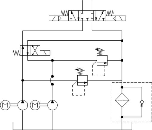
An exemplary scheme
All symbols available in CADprofi program are being inserted as blocks, which can be copied, deleted or edited with the use of standard CAD program commands. Most symbols can be also edited with the use of CADprofi editing commands such as: Quick edit, Edit symbols and Delete symbols.
Symbols are often used to graphically represent real devices, armature and other installations elements, therefore it is possible to add technical parameters, about the products used in the project, to the symbols (Attributes and descriptions command), as well as numbering and symbols' marks. This information can be used when describing drawings when creating graphical legends or specifications.
Program possesses several options that make it easier to insert symbols in the drawing.
|
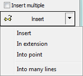
Main options (available after pressing the
•Insert symbol. •Into many lines. •In extension. •Into point. |
|
‘Insert symbol’ option
This is the default option that allows to insert symbols in any point or into a line indicated by user. When inserting symbols into lines, the symbol insertion angle depends on the line angle (the angle specified in the dialog box is being ignored).
6 Procedures
1. Select the symbols from any library.
2. Click the Insert symbol button. The library dialog window will close allowing insertion of symbol into the drawing.
3. Point into a line, in which you would like to insert the symbol.
4. (Optional) Click anywhere in the drawing to insert a symbol.
5. (Optional) Specify the rotation angle of inserted symbol - this option is available only if user has selected the Rotate option in the library dialog window.
|
| |
|
Insert into a line |
Insert in any point |
‘Into point’ option
The Into point option may be used when it is necessary to insert the symbol in a point that lies on a line, but in such a way that the symbol won't "adjust itself to the line". In this option, the inserted symbol "ignores" the line, so it does not break it and it does not take angle from it. This option is used in many situations for example when inserting sensors, which usually need to touch lines.
6 Procedures
1. Select the symbols from any library.
2.
With the use of  button,
pull-down the insertion list.
button,
pull-down the insertion list.
3. Click the Into point button and insert the symbol into the drawing.
4. Point into a point in a line, in which you would like to insert the symbol.
5. (Optional) Click anywhere in the drawing to insert a symbol.
6. (Optional) Specify the rotation angle of inserted symbol - this option is available only if user has selected the Rotate option in the library dialog window.

Inserting a symbol without adjusting it into the line
‘In extension’ option
The In extension option allows to precisely specify the symbol insertion point in relation to other objects located in the drawing. This allows to insert a symbol in a point in accordance with for example another symbol.
6 Procedures
1. Select the symbols from any library.
2.
With the use of button,
pull-down the insertion list.
3. Click the In extension button. The library dialog window will close allowing insertion of symbol into the drawing.
4. Click a line, in which you would like to insert the symbol (P1).
5. Specify the symbol insertion point against you would like to specify the location of the inserted element (P2).
6. Specify an additional offset or click Enter to confirm the insertion point.
7. (Optional) Specify the rotation angle of inserted symbol - this option is available only if user has selected the Rotate option in the library dialog window.
8. Symbol will be inserted in the drawing and the command will end (if user has not selected the Insert multiple option).
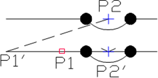
Inserting in extension
‘Into many lines’ option
Into many lines option gives the possibility to quickly insert selected symbol into many lines.
It allows to insert selected symbol into all lines that cross with the „indication line”, that was specified during insertion (P1-P2).

Inserting symbols into many lines
6 Procedures
1. Select the symbols from any library.
2.
With the use of button,
pull-down the insertion list.
3. Click the Into many lines button. The library dialog window will close allowing insertion of symbols into the drawing.
4. Specify the first point of the “crossing line” that will cross with lines (P1).
5. Specify the second point of the “crossing line” that will cross with lines (P2).
6. The selected symbol will be inserted in all lines that crossed with the “crossing line”.
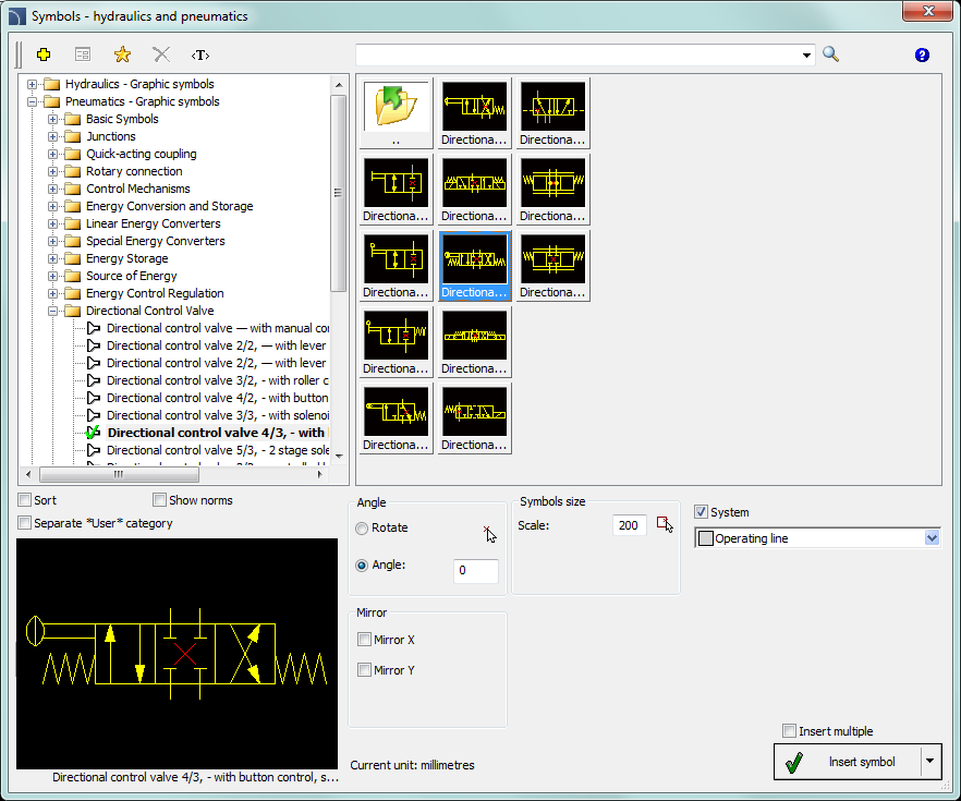
Symbols - hydraulics and pneumatics dialog window
The Symbols - hydraulics and pneumatics dialog window contains the following elements:
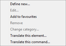
Tools menu:
 Define
new - allows to add a new element to the database. Read more about
it in the Defining user
blocks.
Define
new - allows to add a new element to the database. Read more about
it in the Defining user
blocks.
 Edit - allows to Editing user block parameters.
 Add to
favourites - copies symbol to the *Favourites*.
Add to
favourites - copies symbol to the *Favourites*.
 Delete - deletes the selected symbols from the *Favourites* category.
|
Pop-up menu - options menu for the selected symbol, which is available after right clicking on the mouse button on the selected symbol. Commands in this menu are similar to the tools menu. |
|
Category tree - a set of all categories and symbols in the library, shown as a pull-down tree. User can customize the display order by using the following options:
•Sort - alphabetical order of categories placement and their content.
•Norms- enables/disables displaying symbols according to norms.
Thumbnail view - displays the content of currently selected category as thumbnails.
Preview - displays the preview of the currently selected symbol. Right-clicking on the preview window will zoom the view.
Angle/Rotation - possibility to specify a fixed angle when inserting an element or enabling the rotation option, in which element’s angle is defined by rotation during insertion.
Scale - specifies the size of inserted symbols. It is possible to enter the scale value or to indicate a symbol on the drawing whose scale user would like to use.
System - if in the program options, the extended layer name structure is enabled then symbols will be inserted on layers depending on the kind of installation (system). In case of inserting symbols into an existing line then the System option is being ignored and the symbol layers depends on the line kind.
Mirror X, Y- enabling this option will create an X or Y mirror image for the specified object.
Insert multiple- enables/disables the possibility of inserting multiple symbols to the drawing. The insertion process requires from the user to press the Enter or Esc key when he finished inserting multiple symbols.
6 Procedures
Electronics Workbench V10.0 (often called MultiSIM in later versions) is a circuit simulation and PCB design environment. The “Power Pro Portable” phrasing suggests a portable edition or a portable workstation configuration optimized for power electronics design and testing. Below is concise, structured content you can use for a product page, review, or specification sheet.
The Power Pro edition is a comprehensive toolset for professional-grade electronic design: electronics workbench v10 0 power pro portable
: Users can change component parameters on the fly during a simulation to see immediate effects on circuit behavior. Modern Availability and Alternatives Electronics Workbench V10
Disclaimer: The software title "Electronics Workbench v10.0 Power Pro Portable" typically refers to an unauthorized, "cracked," or modified version of the software designed to run without installation. Electronics Workbench (EWB) was discontinued around 2005 and officially ended at version 10.1. There is no official "Portable" release by National Instruments (the former owners). Using cracked software carries security risks and legal implications. Operating System : Windows XP/Vista/7/8/10 Processor : 1
A defining feature of the software under discussion is its "Portable" nature. In the context of software distribution, a portable application requires no installation; it can be run directly from a USB flash drive or an external hard drive on any compatible Windows computer. This feature addresses a critical logistical challenge in engineering environments. In educational institutions where students often lack administrative privileges to install software on lab computers, or for field technicians who require immediate access to simulation tools on a client's machine, the portable version of EWB V10.0 Power Pro was invaluable. It transformed the software into a truly mobile toolkit, ensuring that an engineer's capability was not tethered to a specific workstation but could be carried in a pocket.

 Creating
pneumatic
schemes
Creating
pneumatic
schemes